ASM Bonding Machine and Its System
ASM die bonding machine is one of the key equipment in the packaging process of LED, chip semiconductor, and camera mounting. As shown in Figure 1, this equipment is a typical high-speed and high-precision fully automated equipment with a vision system on the market.
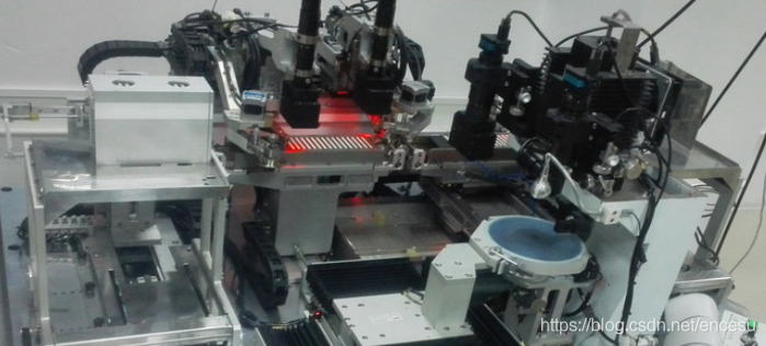
Figure 1 Schematic diagram of die bonding machine
As shown in Figure 2, the ASM die attaching machine is mainly composed of a reclaiming mechanism, a pushing mechanism, a dispensing mechanism, a dispensing platform, a swing arm mechanism, a die attaching platform, a die finding platform, a fixture, and a discharging mechanism. The operation process of the die bond system includes the following steps:
①Image recognition, positioning and image processing of LED chip and LED support board.
②Gluing processing is performed on the given position of the LED bracket board through the silver glue pick-up device.
③Using the chip suction device to accurately place the LED chip at the glue dispensing place. The operating system principle of the equipment includes high-speed precision positioning control, visual positioning control, pneumatic suction control and other related technologies of opto-mechanical integrated systems.
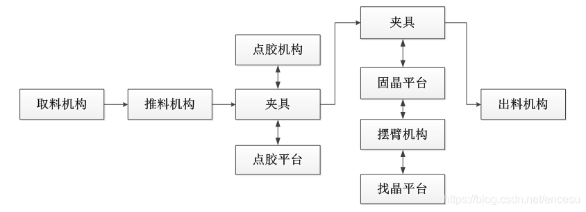
Figure 2 The overall structure of the die bonder
ASM die bonder has many mechanisms, many motors, complex logic, and has high requirements for speed and machine vision. Therefore, a fast and stable template matching algorithm, an efficient multi-target recognition search algorithm, a fast logic processing algorithm, and a convenient and rapid Machine data storage and interactive methods are the key to the die bond control system.
The basic hardware composition of the solid crystal vision control system is shown in Figure 3. The system hardware consists of an industrial camera, an industrial computer, a motion control card, a light source controller, and a dongle. Industrial cameras acquire images; industrial PCs are used for human-computer interaction, motion scheduling and image processing; motion control cards are used for motion control; dongles are used for software encryption.
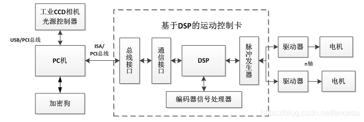
Figure 3 The hardware structure of the die-bonding machine control system
(1) Single-finding and single-bonding
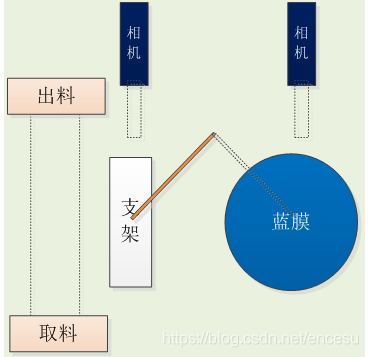
(2) Single-finding and multiple bonding
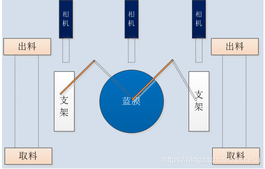
(3) Find more crystals and more solid crystals
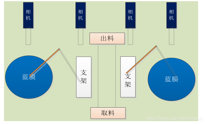
Figure 4 The structure of the die bonding system
ASM die bonding machines can be divided into single-finding and single-die bonding, single-finding and multi-die bonding, and multi-finding and multi-die bonding according to different visual structures, as shown in Figure 4. The ASM die-bonding machine system is complex and requires high-speed and high-precision features. After the project is approved, the design process of the die-bonding system is carried out in stages: software function analysis, hardware system statistics, input and output point allocation and definition, and motor allocation. And definition, motor position analysis, action position interference analysis, alarm situation summary, process parameter collection, manual adjustment button demand analysis, logical object division, logical flow chart drawing, modular coding, testing and delivery.