1. The control logic of the die bond system
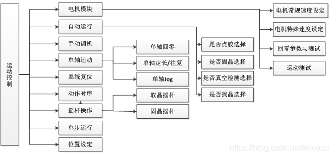
In the motion control part of the solid crystal system example in this article, the drive hardware includes 8 stepper motors, 12 servo motors and 4 linear motors, the output actuator has 24 points, and the input detection sensor has 18 points. The movement of the entire equipment consists of manual adjustment, joystick operation, system reset, single-step movement and automatic operation. The composition of the movement logic system is shown in Figure 7. The manual adjustment is designed to facilitate the debugging personnel to repair the equipment, the joystick operation is to make the movement of the crystal frame more convenient, and the system reset is the output point of the entire equipment and the motor and other actuators return to the original point and safe position, and move in a single step. It is set to control the placement accuracy of a single wafer to facilitate the operation of the test machine, and the automatic operation is a fully automatic die bonding without human operation.

The composition of the motion control system of the die bonder
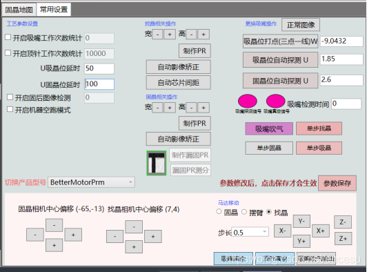
In addition, the manual adjustment machine is composed of the dispensing head 1, the dispensing head 2, the crystal absorption, the crystal bonding, the feeding and the discharging many small pieces of logic, a total of 63, the operation page of the manual adjustment is shown in Figure 8. Each small segment of logic is part of the movement of the whole machine, which is equivalent to taking some sections of the whole machine's logic to make a single action according to the mechanism.

Manual debugging actions
The die-bonding motion system includes 2 groups of dual-axis planar moving array mechanism platforms for dispensing positioning, 1 group of die-bonding dual-axis planar moving array mechanism platforms, and 1 group of dual-axis position moving mechanism platforms for searching and dynamically calculating the target position of the die And so on, these 4 groups of platforms constitute the most difficult part of the logic of the die bonding system. Carry on the logical object division to the die-bonding machine movement system,
2. Logic design of die bonding system
1. Design examples of dispensing mechanism and platform movement
In view of the complexity of die-bonding motion control and the limited space of this article, this article only describes the design of the dispensing mechanism and dispensing platform. The dispensing organization is responsible for dispensing, and the dispensing platform is responsible for moving the glue cup. The two cooperate to form the glue dispensing system of the die bonder. The logic flow chart of the dispensing mechanism is shown in Figure 6-11. The movement process of the dispensing logic object is completed by the up and down dispensing and the left and right swing. After dispensing the glue, it interacts with the platform, and the platform moves and reciprocates until the platform position is completed.
The action flow chart of the logic object of the dispensing platform is shown in Figure 9. When the logic object of the dispensing logic enables the dispensing platform to move, the movement platform will perform accurate positioning along with the movement of the CCD vision camera. Two glue-dispensing logic objects and two dual-axis positioning platform objects have the interaction of enabling pins between them.